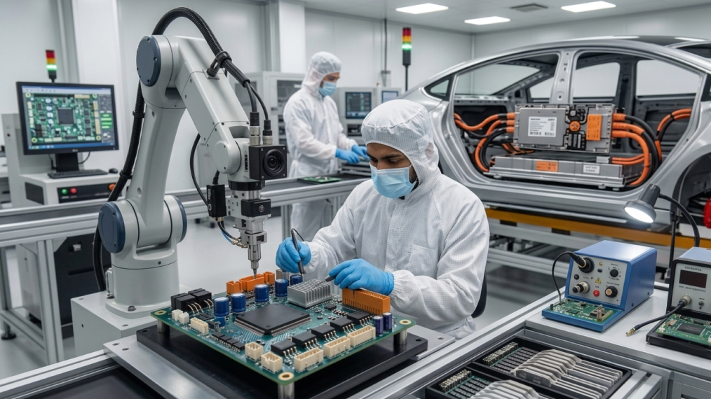
An EV runs on a lot more than a battery and a motor. Behind the scenes, there are circuit boards quietly handling battery monitoring, motor control, charging, power conversion, thermal management, and communication. You don’t really notice them when everything works. But they’re doing a lot.
That’s what makes automotive PCB assembly such an interesting part of EV electronics. It’s not simply about putting components onto a board and sending it down the line. Layout, component selection, soldering, thermal management, inspection, and testing all come together here.
For hardware teams, the real work often starts when a design has to move from a prototype to something that can be built consistently at production scale. That’s where the small manufacturing details start to matter. And there are plenty of them.
Where PCB Assembly Fits in an EV
An EV has several electronic systems doing different jobs. The battery management system watches cell voltage and temperature. The inverter manages motor power. The on-board charger handles incoming power, while DC-DC converters support lower-voltage electronics.
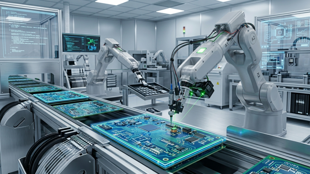
These systems can put power devices, sensors, microcontrollers, communication interfaces, and protection circuits onto compact boards. The flow is familiar: solder paste is printed, components are placed, boards go through reflow, then assemblies are inspected and tested.
Simple on paper. Less simple when every detail has to be repeatable.
Component Placement Is an Engineering Decision
Component placement is not just about making everything fit. In EV power electronics, component placement can affect electrical performance, heat flow, manufacturability, and serviceability.
High-current paths need suitable copper and short connections. Sensitive control circuits may need separation from noisy power sections. Heat-producing components need a sensible thermal path.
DFMA, or Design for Manufacturing and Assembly, helps engineers check placement consistency, inspection access, and testability.
Finding these things during design is far cheaper than finding them after a production order.
Building for EV Power Conversion
Power electronics can include MOSFETs, IGBTs, diodes, capacitors, inductors, sensors, and connectors. Some carry significant current and generate plenty of heat, so assembly has to account for electrical and mechanical demands together.
That may mean heavier copper, larger terminals, reinforced joints, or additional thermal structures.
This is why PCB manufacturing and assembly should be planned together. A circuit can work perfectly on a schematic and still need changes before it becomes a repeatable production build — the same DFMA thinking that applies to turnkey electronics manufacturing more broadly.
Automated PCB Assembly and Process Control
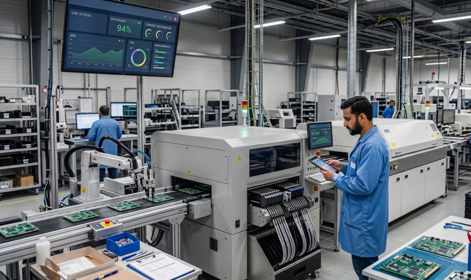
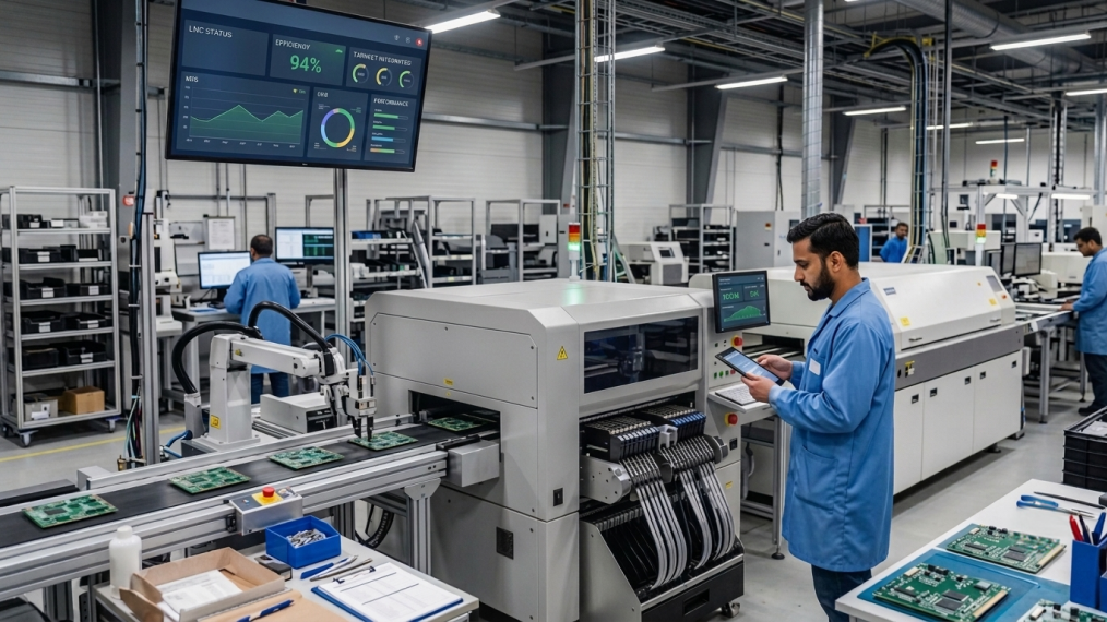
Automation makes sense when the same board is built repeatedly. Automated PCB assembly improves consistency in placement, solder paste application, and production records.
Still, machines aren’t magic. Feeder setup, stencil condition, solder paste handling, placement accuracy, and reflow temperature all need control. Small process drift can quietly become a production issue if nobody catches it.
Traceability helps. When the BOM, component lots, inspection results, and test data are connected, supply chain visibility improves. Teams can trace what went into a board without hunting through spreadsheets.
Inspection Is Part of the Build
Inspection works best as part of the process, not just a final checkpoint.
- AOI: Checks component presence, orientation, placement, and visible solder conditions. It catches obvious issues quickly and consistently.
- X-ray inspection: Examines hidden joints under packages such as BGAs.
- Electrical testing: Checks whether the assembled circuit meets defined electrical requirements.
- Functional testing: Runs the board through relevant operating conditions to check system behavior.
Not every board needs the same inspection mix. The plan should follow package types, reliability requirements, and manufacturing risks.
Moving From Prototype to Production
A prototype can survive hands-on attention. Production needs discipline.
BOMs have to be controlled. Components need qualification. Work instructions need to be clear. Test coverage needs to be repeatable.
A good printed circuit assembly process keeps engineering and manufacturing connected instead of making them teams that only talk when something goes wrong.
BOM optimization matters too. Two parts may look interchangeable but differ in package, lifecycle status, availability, qualification, or sourcing options. Those details can affect production later.
For product companies, circuit board assembly is part of supply chain strategy, not just a factory task. The build should stay practical as volumes rise.
Elecbits: Turning Electronics Designs Into Production-Ready Builds
Once an EV electronics design moves beyond the engineering desk, a lot starts happening in parallel. The BOM needs to be ready, components have to be sourced, manufacturing requirements need to be checked, and the finished boards still need proper inspection and testing.
This is where having one connected partner can make things easier. Instead of managing several vendors and passing information back and forth, design, sourcing, assembly, and testing can stay connected throughout the build, following the same turnkey manufacturing approach that helps hardware teams scale without losing control.
That’s the approach we take at Elecbits. We’re an end-to-end electronics design and manufacturing platform, supporting teams from component sourcing and PCB manufacturing and assembly to testing and production. Companies and brands including Maruti Suzuki, Siemens, Ola Electric, and Motherson trust Elecbits for their electronics requirements.
For EV power electronics, that connection matters. Engineers get manufacturing feedback, supply chain teams get better visibility, and manufacturing teams get clearer inputs. The result is a more practical path from design to production.
Conclusion
EV electronics are becoming more integrated, compact, and software-driven. The PCB remains the meeting point for power, sensing, control, and communication.
Assembly becomes part of the engineering conversation, not something that starts after design.
The best approach isn’t simply maximum automation or maximum inspection. It’s the right combination of design decisions, components, assembly controls, testing, and sourcing discipline.
A printed circuit board assembly process should do two things well: build a board that works, and keep building it that way as production grows.


 Resources Quality standards Reliable methods to keep our quality consistent. Blog Deep dive into market-moving trends.